There is a need to develop an automatic curtain opening and closing system which is effortless, hands-free operation for daily routines, particularly benefiting the elderly, individuals with limited mobility, or for operating high, large, or hard-to-reach curtains.
| SN | Full Name | Roll | Email ID | Contact No |
|---|---|---|---|---|
| 1 | Sarvadnya Patil | 209 | 02fe25bcs017@kletech.ac.in | 8861470978 |
| 2 | Kashif Ahmad | 208 | 02fe25bcs013@kletech.ac.in | 9559349677 |
| 3 | Shreya Uppar | 227 | 02fe25bcs093@kletech.ac.in | 8749078857 |
| 4 | Neha Bagale | 228 | 02fe25bcs094@kletech.ac.in | 6361068644 |
| 5 | Nagaratna Myageri | 229 | 02fe25bcs095@kletech.ac.in | 8088921052 |
1. What did you do in the activity?
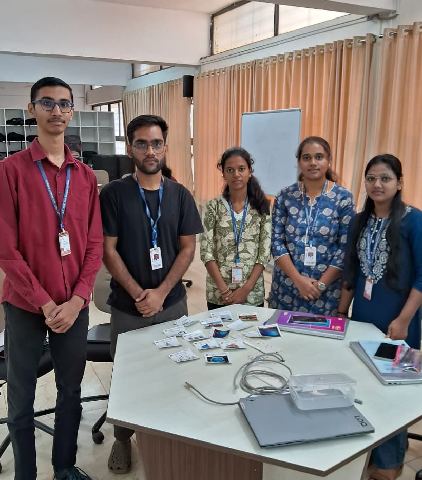
I worked with my team to identify duplicate cards, discussed possible trade options, and communicated with other teams to find a suitable exchange. Since we were allowed only one trade in total and had a 10-minute limit, we planned carefully, negotiated with another team, completed our single card exchange, and then organized our final set before time ended.
2. Did the activity help you? How?
Yes. I learned to communicate better by discussing with my team and interacting with other teams to make decisions quickly.
3. Any challenges you have faced?
Yes. The main challenges were the limited 10-minute time and being allowed only one trade, which made it difficult to decide the best strategy quickly. It was also challenging to find a team willing to exchange the card we needed.
4. Share your reflections here.
The activity was engaging and helped me improve my communication and teamwork skills. Working under time pressure taught me to think quickly and collaborate better with others.
1. What is your understanding of the sewage problem in Bangalore?
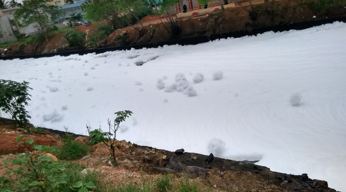
Bangalore faces a growing sewage problem, threatening the city. Rapid growth and urbanization lead to excessive sewage, overwhelming infrastructure. Untreated sewage contaminates water sources, causing pollution, health risks, and environmental damage. Immediate action is needed to taken treatment facilities, research solutions, and implement sustainable waste management.
2. What are the root causes of this problem?
The root causes of this problem include: too many people, businesses breaking rules, and citizens lacking knowledge of proper waste disposal habits. Other contributing factors are rapid population growth, old pipes and treatment plants. The situation worsens when industries ignore government regulations, polluting water and overloading facilities. Furthermore, poor public knowledge about proper disposal methods leads to blocked pipes, causing overflows. Chemical factories pose a critical danger, as their toxic waste kills cleaning bacteria in treatment plants, corrodes pipes, and harms aquatic life due to the lack of required pretreatment.
3. What are the possible solutions for this?
To fix the pollution, we need strong control measures. This means making sure factories treat their toxic waste first and giving harsh penalties if they don't. We also need to fix and maintain our infrastructure. Teaching people how to properly dispose of waste is super important. Industries should have their own sewage systems. We need to plan new buildings and population growth carefully, and have safe places for chemical waste.
4. Share your reflections here.
I've found a big problem, mainly in those huge cities. It's a major issue for cities worldwide, because of things like complicated infrastructure and super fast growth. Now I'm going to figure out how this problem shows up in these cities and come up with some good solutions.
1. Describe the problem.
Street lights in many areas remain switched on throughout the night even when no pedestrians or vehicles are present. This results in unnecessary electricity consumption, increased operational costs, and avoidable environmental impact. The lack of automation or smart control means lighting is not adjusted based on real-time usage. Addressing this issue can significantly reduce energy wastage by ensuring street lights operate only when needed, while still maintaining public safety and visibility.
2. Mention which all disciplines are involved.
Electrical Engineering, Electronics Engineering, Computer Science / IT, Mechanical Engineering
This module is vital because as it prepares for the project. It specifically focuses on teaching key professional skills, such as working effectively in a team, setting clear goals, managing time efficiently, and mastering clear communication and professional interaction.
In your opinion, what are the benefits of working in a team?
Benefits of teamwork
Can you provide examples of how teamwork contributes to the success of a project?
1. What is scrum methodology and how does it fit into the agile framework?
Scrum is a super helpful, easy way to manage tough projects. It follows Agile ideas and helps teams get things done by breaking them into small bursts called sprints. During sprints, a team with all the skills needed works together to make something useful. The whole thing is about being open, checking in, and changing things up as needed through meetings, and it includes roles like a Product Owner, Scrum Master, and developers.
2. What is a sprint in the context of Agile development?
In Agile development, especially with Scrum, a sprint is like a short, timed burst, usually lasting 1 to 4 weeks. It's the project's main rhythm, giving a specific time to finish important tasks, which helps get rid of any problems and makes the project a success.
3. How do you envision using Agile principles, scrum, and sprint in your course project?
We'll divide the project tasks, giving each team member specific things to do. This way, we can easily adjust and check in often. We'll have quick discussions to make sure everyone's on the same page. After each one, we'll show our progress, get feedback, and plan what to do next.
1. What were your initial thoughts and feelings about the activity?
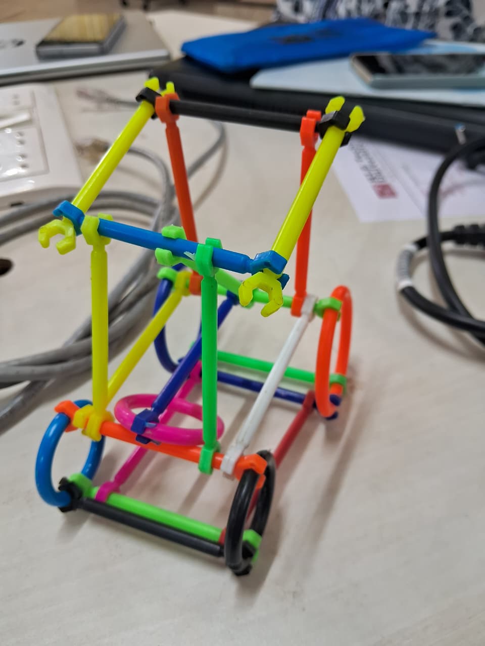
My first thought was to make a strong base. I figured out how to join the sticks to make the inside frame, and then built the main part of the car around that.
2. What challenges did you encounter during the activity?
I faced a challenge designing the steering mechanism.
3. How did your team approach problem-solving and decision-making?
My team assessed the necessary materials and considered efficient problem-solving approaches. We then decided to implement a specific solution, which we believed would resolve the issue effectively.
4. What did you learn from the activity that you can apply to future projects or teamwork situations?
I learned that you can't do a project alone - it takes everyone's skills. Each person has a part to play, and a team is key. I know now that it's super important to get along with your team, communicate well, set goals, manage our time, plan things out, make decisions, build something good, and support each other.
1) How did the collaborative exploration of various design concepts within you team contribute to a more comprehensive understanding of creative problem-solving in engineering design?
2) Reflect on the significance of selecting a design concept that aligns with functional requirement and ethical considerations.
3) In what ways considering alternative design approaches enhance your ability to address complex engineering challenges?
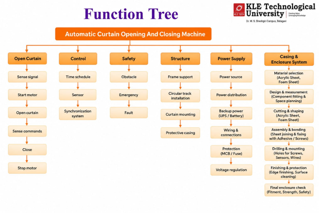
Describe how the collaborative nature of the role-play activity influenced the team's ability to systematically define and approach engineering problems by identifying objectives, functions, and constraints.
| SN | Objectives | Functions | Constraints |
|---|---|---|---|
| 1 | Approximately 5 years lifespan | Automatically open and close the curtain | Compact design (minimal space) |
| 2 | Smooth and steady movement | Easy and effortless operation | Open/close within 10 seconds |
| 3 | Obstacle detection sensor | Smooth circular motion | Total cost: ₹1500–₹2500 |
| 4 | Safe operation without risk | Motor speed control mechanism | AC power supply (220–240 V) |
| 5 | - | Circular track or guide rail system | Light to medium-weight curtains |
| 6 | - | - | Timer setting needed |
Design and develop an automatic circular curtain opening and closing system for a statue that can operate smoothly and safely. The system should automatically open and close light to medium-weight curtains in smooth circular motion within 10 seconds using a motor speed control mechanism and obstacle detection sensor for safety. It should ensure easy and effortless operation, compact installation, and smooth, steady movement. The system must operate on an AC power supply (220–240 V), use a circular track or guide rail system, and have a durability of about 5 years. The total installation cost should be between ₹1500 and ₹2500, ensuring safe and reliable operation without risk to users.
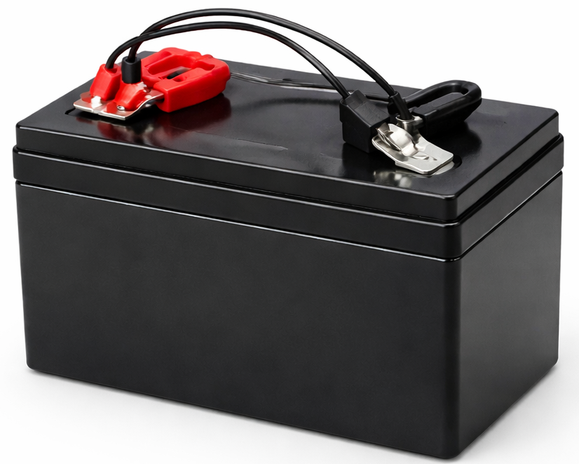
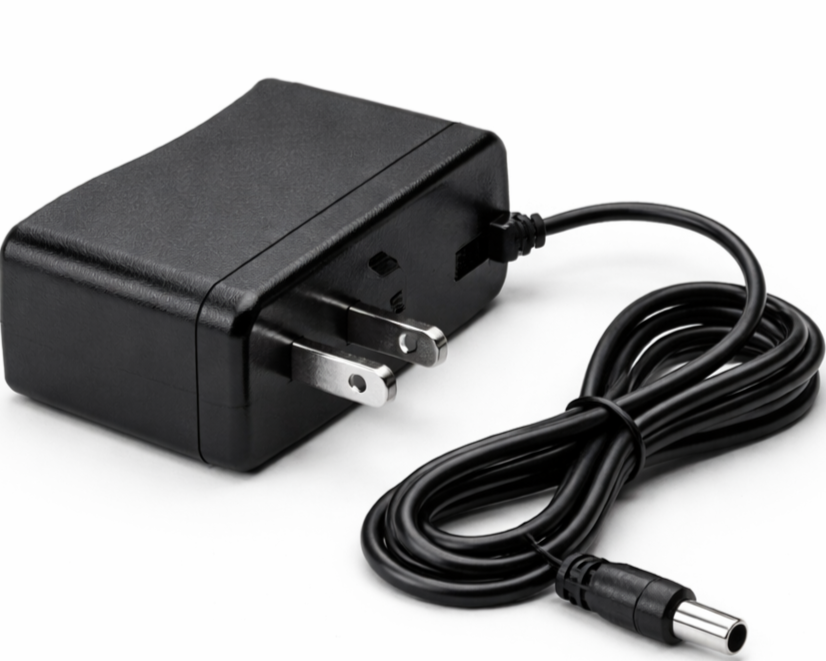
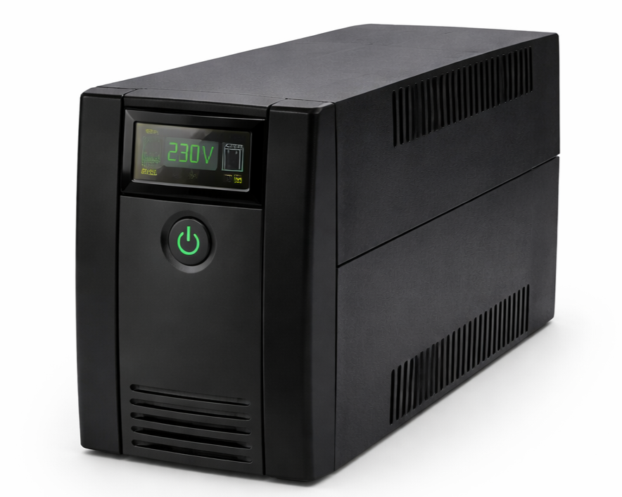
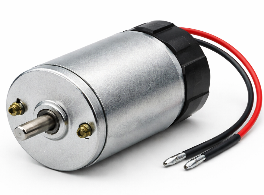
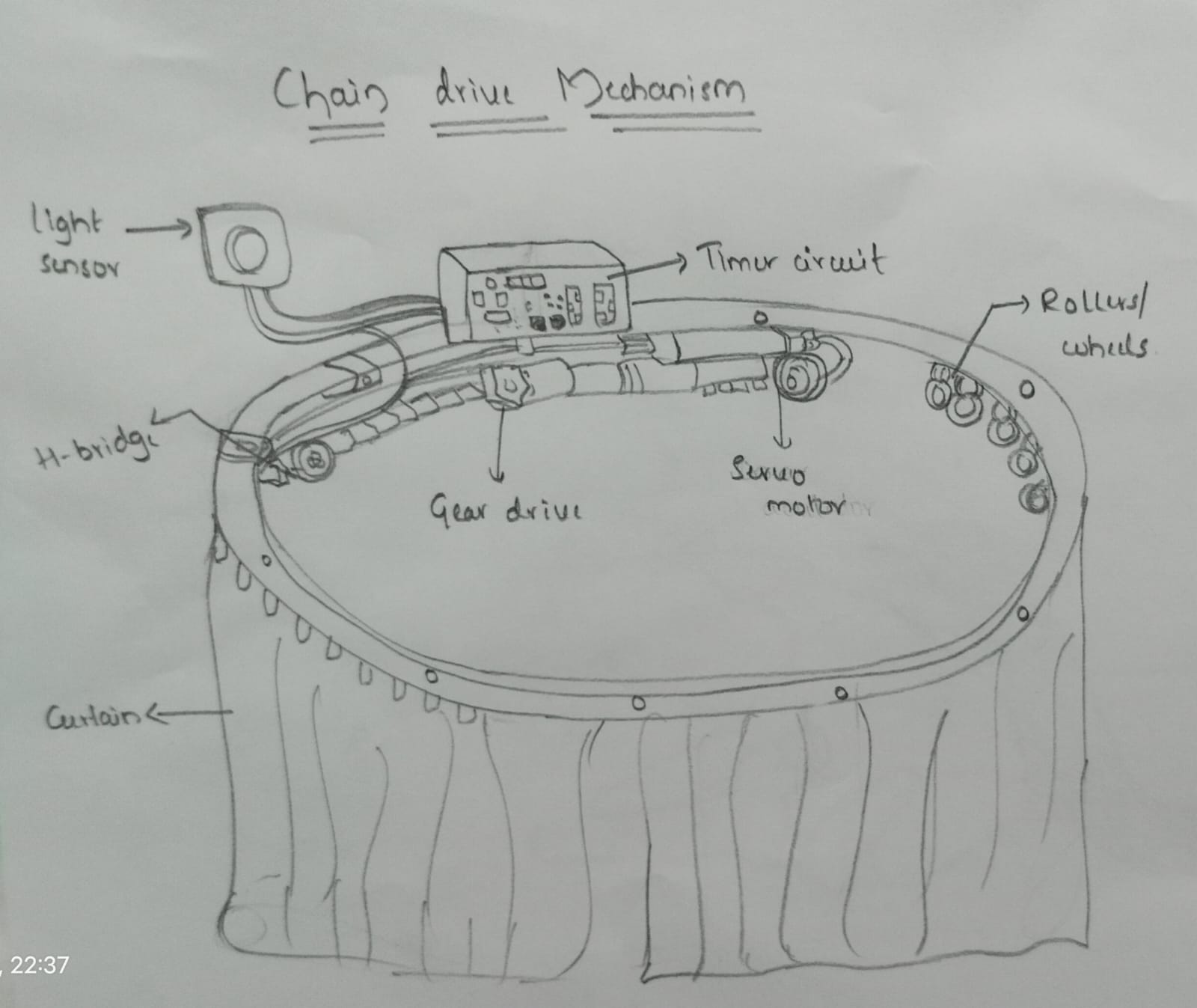
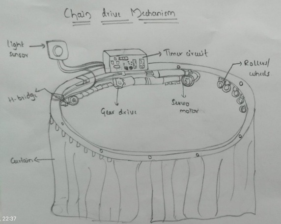
Design and develop an automatic circular curtain opening and closing system for a statue to ensure smooth and safe operation. The system should open and close light to medium-weight curtains in a circular motion within about 10 seconds. Various concepts are generated by selecting appropriate sub-functions and means such as sensors, control systems, power supply, actuators, and transmission systems. The system may operate using light sensors, motion sensors, or manual input. Control can be achieved through switch, timer circuit, remote control, or web-based systems. It should operate on suitable low-voltage power sources such as battery, adapter, or solar power. A circular track or guide rail must be used to ensure smooth and continuous curtain movement. Proper direction control and safety should be ensured using H-bridge or motor drivers along with limit switches or obstacle sensors. The system should be compact, cost-effective (₹1500–₹2500), durable for about 5 years, and easy to install and operate.
Design and develop an automatic circular curtain opening and closing system for a statue with an integrated IR-sensor based detection system and Arduino control logic. The system will use a high-torque 12V Gear Motor and a professional Circular Rail system to ensure smooth, consistent torque and safe circular motion within 10 seconds. Power will be managed through a regulated 12V 2A Adapter, ensuring reliable year-round operation. Safety features will include dual hardware Limit Switches and a software-based Obstacle Detection system for comprehensive collision avoidance. The final solution is optimized for a ₹2500 budgetary constraint, designed for a 5-year maintenance-free lifecycle with a priority on safe, easy, and effortless operation for high-traffic or hard-to-reach installations.
| Sub-function | Means 1 | Means 2 | Means 3 | Means 4 | Means 5 |
|---|---|---|---|---|---|
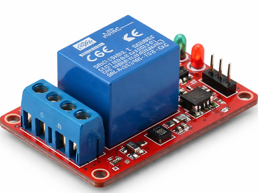
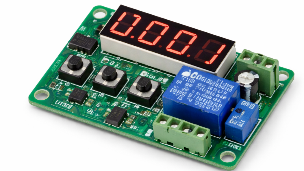
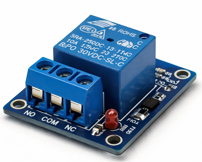
| CONTROL SYSTEM | Relay Module |
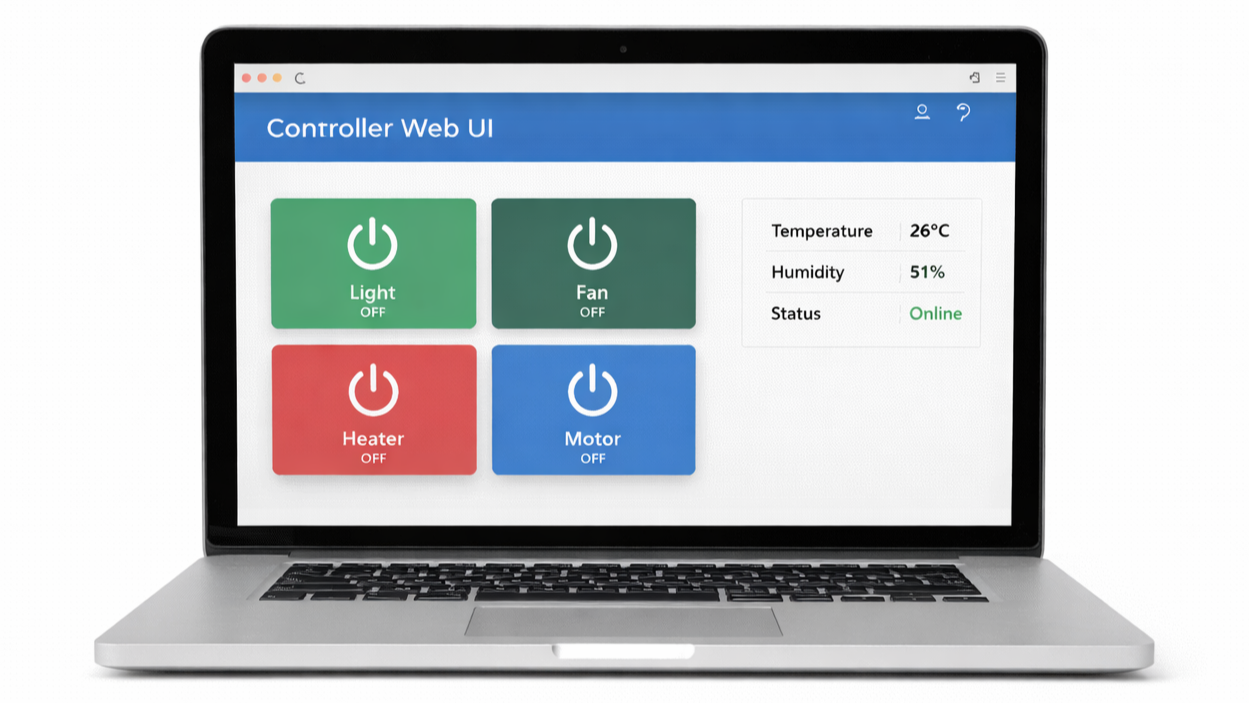
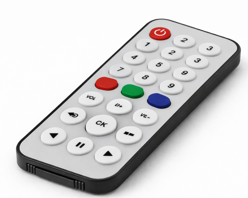
Web Based Control |
Remote Control |
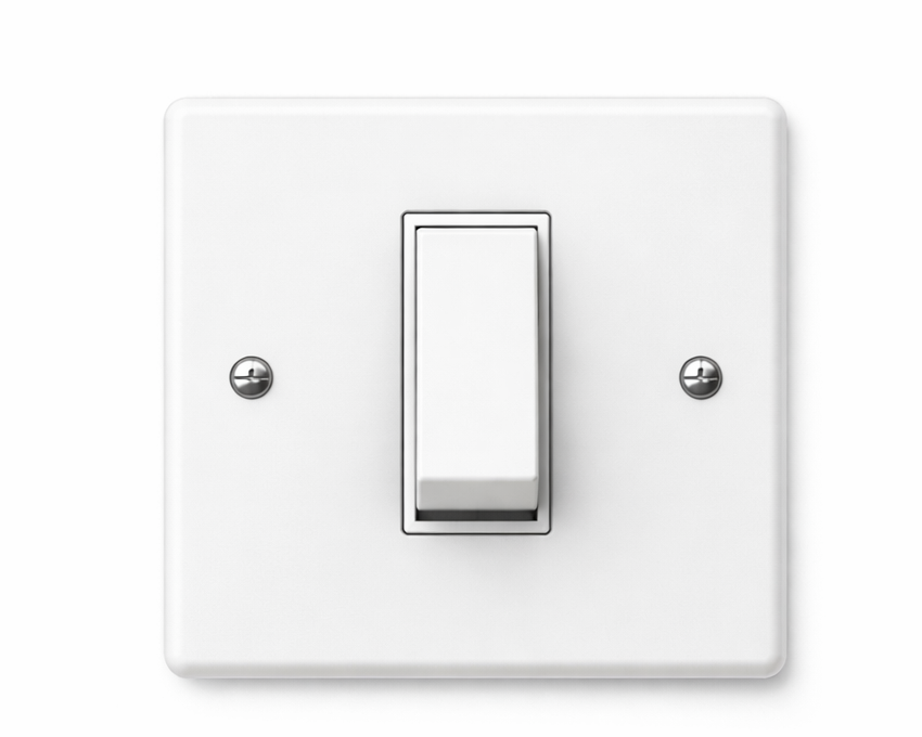
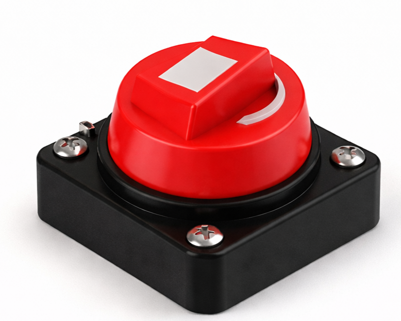
Switch |
Timer Circuit |
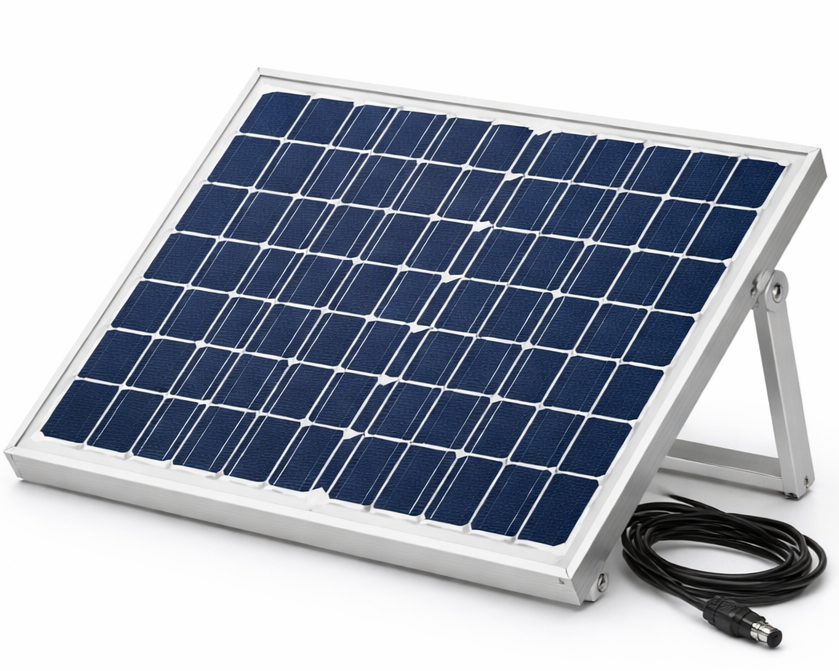
| POWER SUPPLY | Solar Panel |
Battery |
Adapter |
UPS |
|
| ACTUATORS | DC Motor |
Stepper Motor |
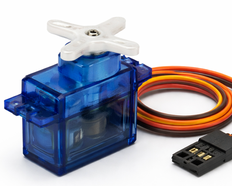
Servo Motor |
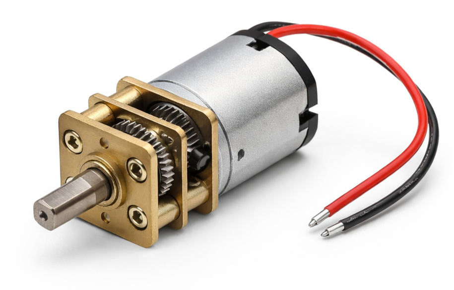
Gear Motor |
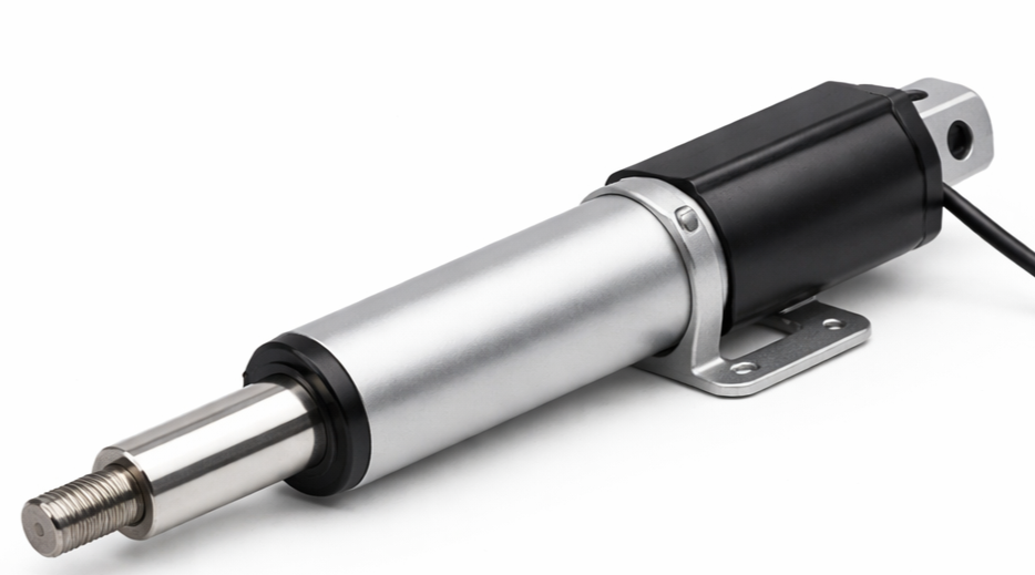
Linear Actuator |
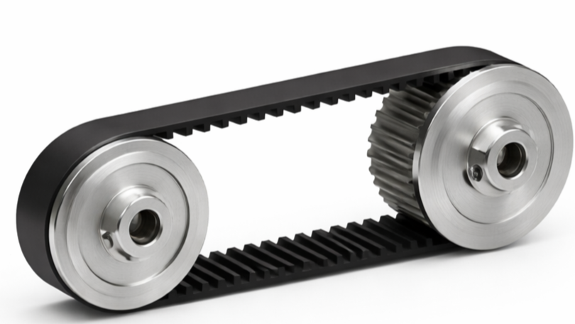
| TRANSMISSION SYSTEM | Belt Drive |
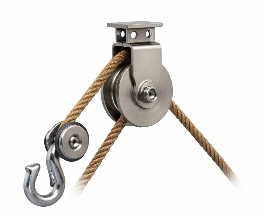
Pulley & Rope |
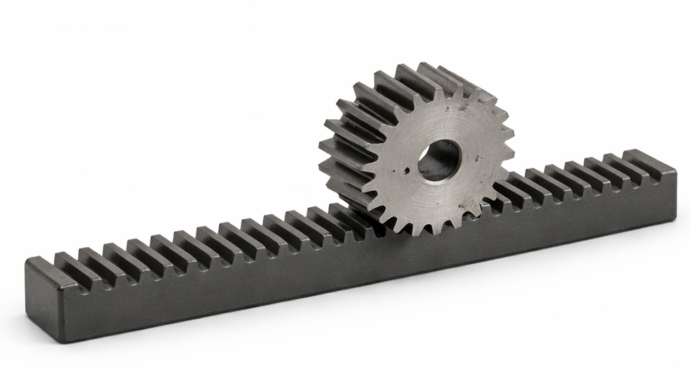
Rack & Pinion |
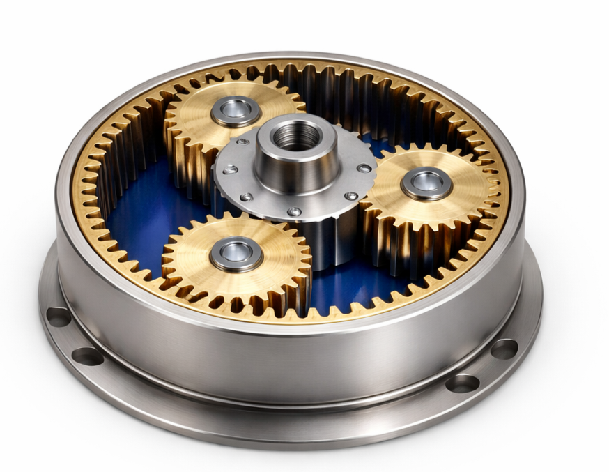
Epicyclic Gear Train |
Gear Drive |
| GUIDING SYSTEM | Sliding Channel |
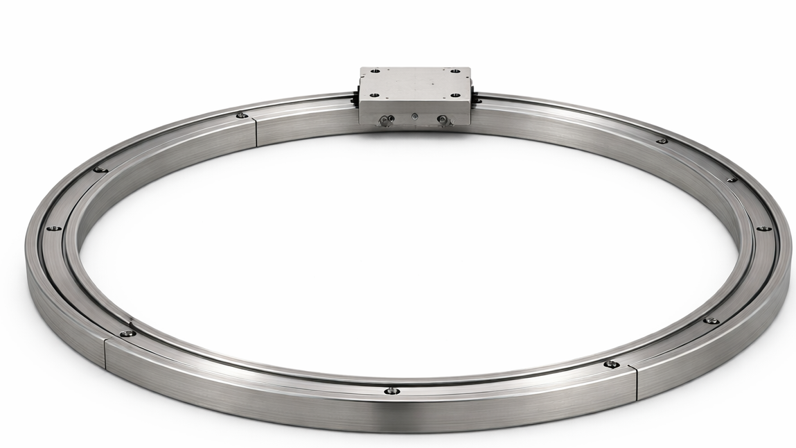
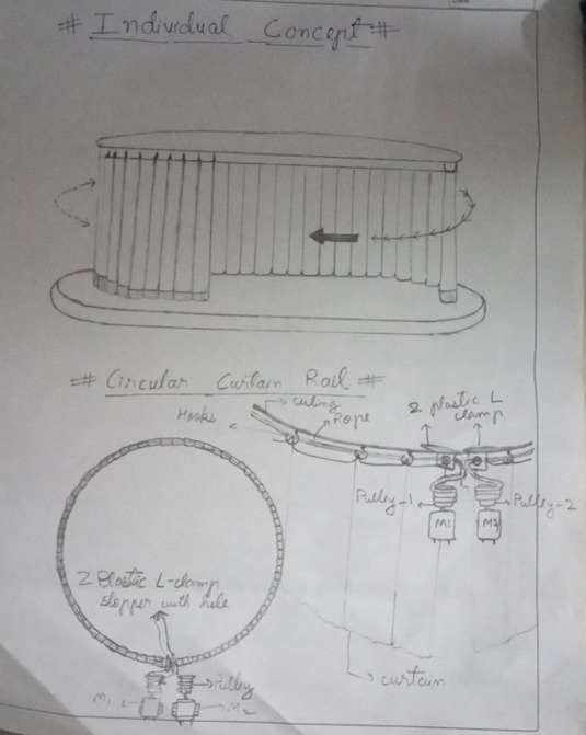
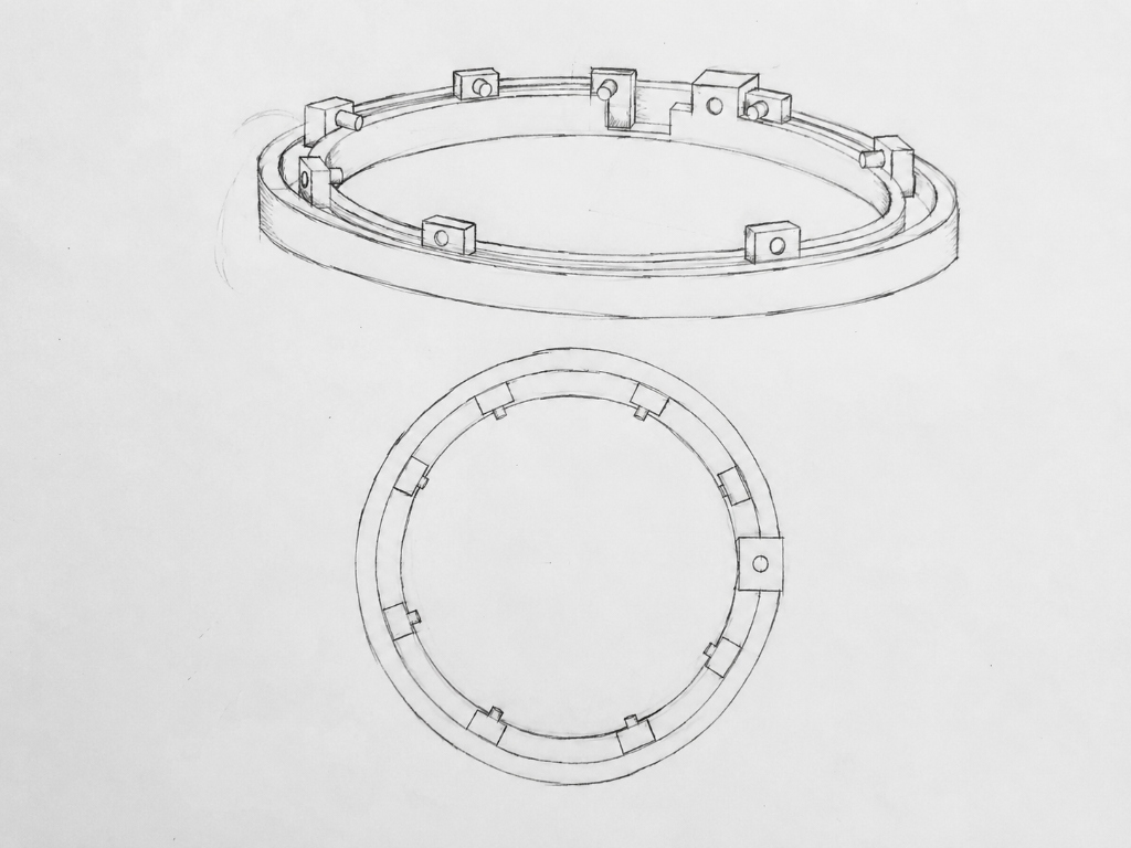
Circular Track Rail |
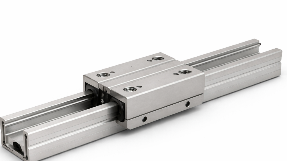
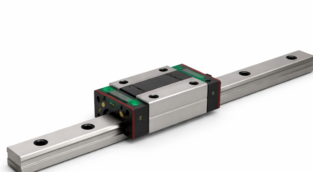
Linear Guide |
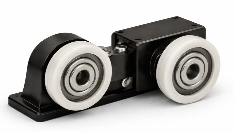
Wheel Rollers |
|
| DIRECTION SYSTEM | H-Bridge |
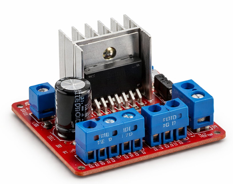
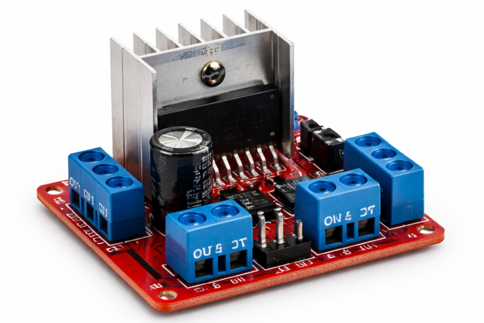
L298N Motor Driver |
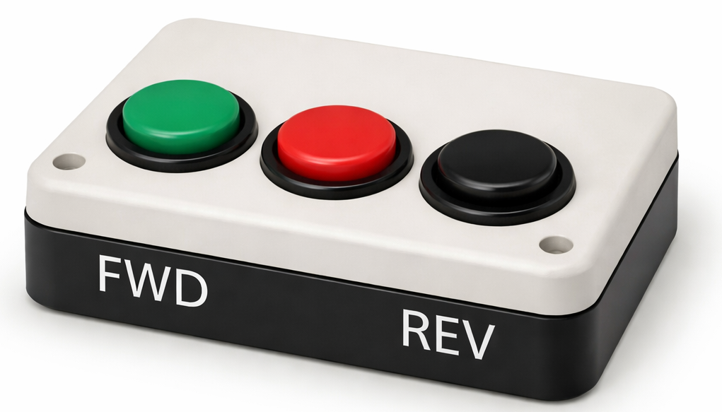
Forward/Reverse Control |
Relay Switch |
Polarity Switch |
| Design Objectives | Weights |
|---|---|
| Safety | 9 |
| Cost effectiveness | 7 |
| Ease of installation | 8 |
| Compact Design | 7 |
| Energy efficiency | 6 |
| Circular Operation | 10 |
| Automatic Control | 9 |
| Design Objectives | Weights | Design 1 | Design 2 | Design 3 | Design 4 | Design 5 (Datum) |
|---|---|---|---|---|---|---|
| Safety | 9 | 0 | 0 | 0 | + | Datum |
| Cost effectiveness | 7 | - | + | 0 | 0 | Datum |
| Ease of installation | 8 | + | 0 | + | - | Datum |
| Compact Design | 7 | 0 | 0 | 0 | 0 | Datum |
| Energy efficiency | 6 | 0 | + | 0 | 0 | Datum |
| Circular Operation | 10 | ++ | 0 | + | ++ | Datum |
| Automatic Control | 9 | - | 0 | - | - | Datum |
| Score (+) | 28 | 13 | 18 | 29 | 0 | |
| Score (-) | 22 | 8 | 15 | 17 | 0 | |
| Total | 6 | 5 | 3 | 12 | 0 | |
| Design No. | Objective | Score | Justification for the Score |
|---|---|---|---|
| 1 | Safety | + | Provides safe operation with basic protection |
| Cost effectiveness | 0 | Moderate cost, no major advantage | |
| Ease of installation | 0 | Standard installation effort | |
| Compact Design | - | Slightly bulky design | |
| Energy efficiency | 0 | Average energy usage | |
| Circular Operation | ++ | Very smooth and efficient circular motion | |
| Automatic Control | - | Limited automation capability | |
| 2 | Safety | 0 | Basic safety, no enhancement |
| Cost effectiveness | + | Low-cost components used | |
| Ease of installation | 0 | Standard installation effort | |
| Compact Design | 0 | Moderate size | |
| Energy efficiency | + | Efficient power usage | |
| Circular Operation | 0 | Average motion performance | |
| Automatic Control | 0 | Limited control features | |
| 3 | Safety | 0 | No added safety feature |
| Cost effectiveness | 0 | Moderate cost | |
| Ease of installation | + | Easy to install | |
| Compact Design | 0 | Normal size | |
| Energy efficiency | 0 | Higher power consumption | |
| Circular Operation | + | Good circular motion | |
| Automatic Control | - | Weak control system | |
| 4 | Safety | 0 | Acceptable safety level |
| Cost effectiveness | - | Slightly expensive | |
| Ease of installation | + | Easy installation | |
| Compact Design | 0 | Balanced structure | |
| Energy efficiency | 0 | Average efficiency | |
| Circular Operation | ++ | Excellent circular movement | |
| Automatic Control | - | Limited automation | |
| 5 | Safety | Datum | Reference Design |
| Cost effectiveness | Datum | Reference Design | |
| Ease of installation | Datum | Reference Design | |
| Compact Design | Datum | Reference Design | |
| Energy efficiency | Datum | Reference Design | |
| Circular Operation | Datum | Reference Design | |
| Automatic Control | Datum | Reference Design |
DESIGN 4
Based on the Pugh Chart analysis, Design 4 achieved the highest total score of 12. Its superior circular operation (++) and robust safety features (+) outweighed its slightly higher installation complexity and automatic control limitations.
1. Define basic linkage mechanisms and its component.
A linkage mechanism is a mechanical system made of rigid bodies (links) connected by joints (kinematic pairs) to transmit motion and force. The basic components include:
2. Briefly explain the real-life applications of linkage mechanisms.
| SN | Mechanism Type | Description |
|---|---|---|
| 1 | Four Bar Mechanism | Consists of four rigid links connected in a closed loop. Variants include Crank-Rocker, Double Crank, and Double Rocker depending on the link lengths (Grashof's condition). |
| 2 | Crank Slider Mechanism | Converts rotary motion into linear reciprocating motion (or vice versa). Commonly found in internal combustion engines, compressors, and pumps. |
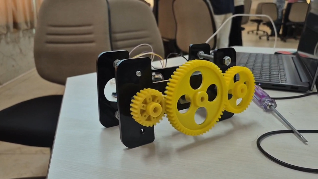
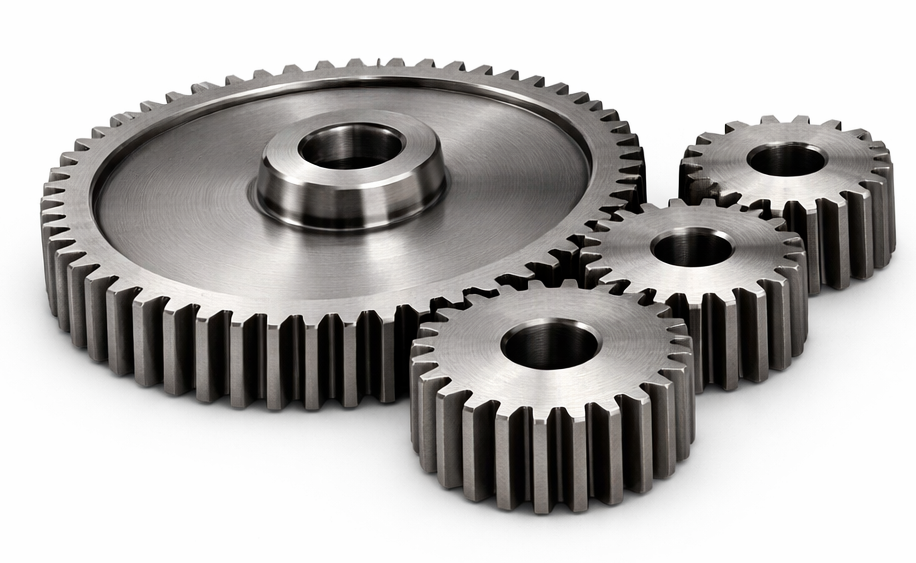
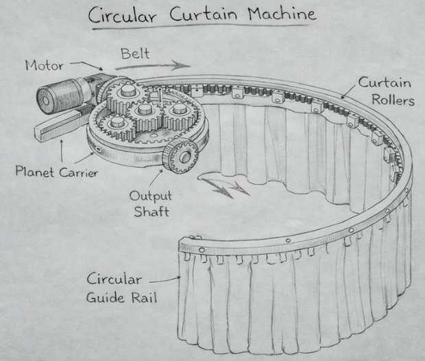
Gear mechanisms transmit torque and rotational motion between shafts using toothed wheels. They offer precise speed ratios, high efficiency, and the ability to change direction of rotation. Common types include spur gears, helical gears, bevel gears, and worm gears.
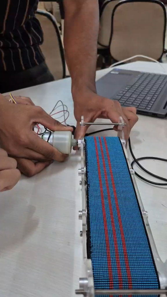
A conveyer belt mechanism uses a continuous loop of material (belt) stretched over two or more pulleys to transport objects from one location to another. Widely used in manufacturing, mining, and logistics for material handling and assembly line operations.
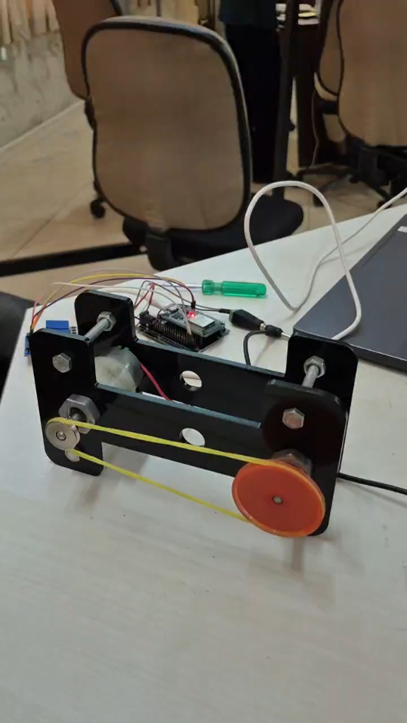
Belt and pulley systems transmit power between two shafts using a belt wrapped around pulleys. They allow speed variation, shock absorption, and can connect shafts at different distances. Commonly found in industrial machines, vehicles, and domestic appliances.
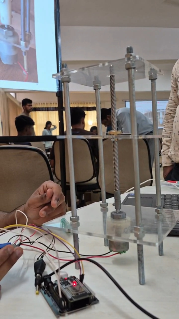
A lead screw mechanism converts rotational motion into linear motion using a threaded shaft and a nut. It provides precise positioning with high mechanical advantage. Used in CNC machines, 3D printers, vices, and linear actuators for accurate displacement control.
The virtual implementation of the automatic curtain system involves creating digital prototypes and circuit simulations to validate the design before physical construction. This includes 3D modeling of the mechanical assembly and electronic circuit design for the control system.
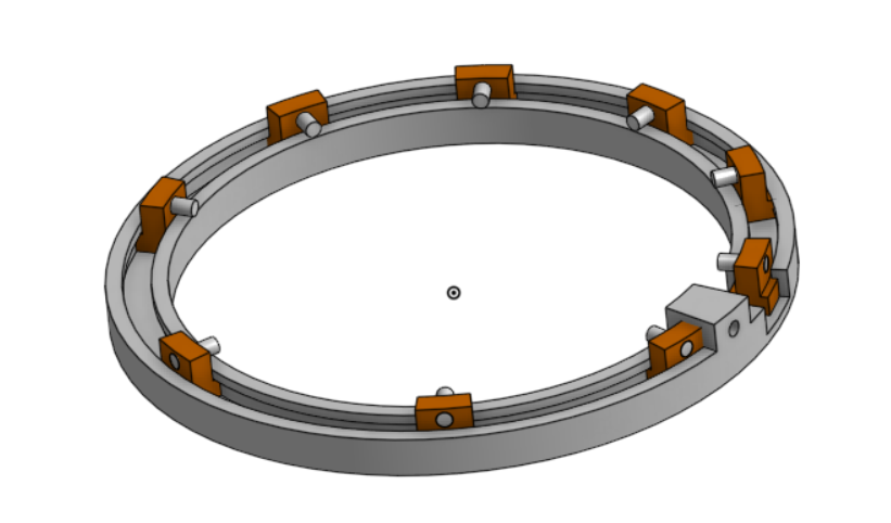
OnShape 3D CAD Assembly Model: Shows the circular track rail assembly complete with structural guide brackets and sliding rollers designed for the automatic curtain mechanism.
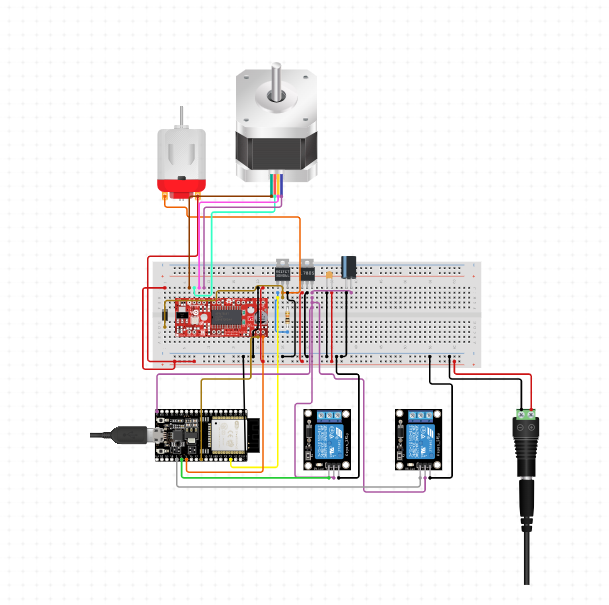
Fritzing Circuit Schematic Diagram: Shows the ESP32 microcontroller interfaced with a NEMA 17 stepper motor, a standard DC motor, dual relay modules, linear voltage regulators (7805), and an H-bridge driver circuit, powered by an external 12V supply adapter.
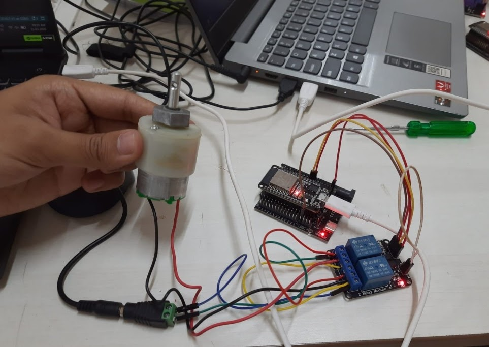
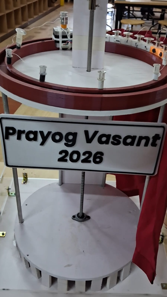
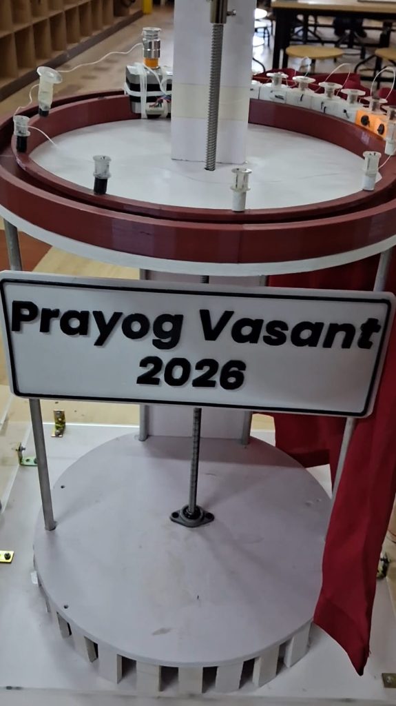
The physical prototype transforms our virtual 3D models and circuit designs into a tangible, working system. It integrates high-precision structural elements with digital sensors and actuators to achieve silent, reliable curtain operation on a circular track layout.
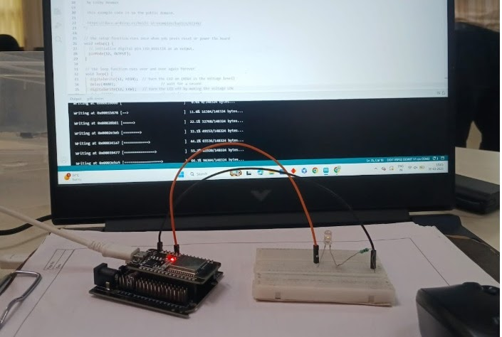
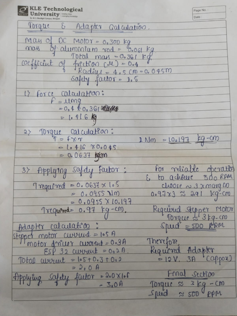
Handwritten Torque & Adapter Calculations Reference Sheet: Outlines the physical force and torque parameters (T ≈ 3 kg-cm, N ≈ 500 RPM) and electrical current parameters (I ≈ 3 A at 12 V) required for the physical implementation.
1. What challenges did you encounter while programming the ESP32, and how did you overcome them?
Programming the ESP32 presented several challenges, primarily involving pin multiplexing conflicts and multi-threaded execution stability.
• Pin Conflicts & GPIO Selection: The ESP32 has specific bootstrap pins (e.g., GPIO 0, 2, 5, 12, 15) that can cause boot loops if held high/low during startup. We encountered boot failures when first connecting the IR sensors to these pins. We solved this by consulting the ESP32 pinout reference and remapping our inputs to safe general-purpose inputs (GPIO 13, 14, 27).
• Non-blocking Code: Integrating the LDR light readings, IR sensor polling, and motor speed control using standard delay() functions caused the system to become unresponsive to real-time safety triggers (obstacle detection). We overcame this by refactoring the codebase to use non-blocking timing with the millis() function.
2. Describe a specific moment during the ESP32 programming process when you had to troubleshoot and debug your code.
During the integration of the IR obstacle sensor and the motor driver (L298N), we noticed the DC motor would intermittently run at maximum speed or lock up entirely when the sensor detected an object, instead of stopping instantly.
To troubleshoot, we first isolated the components:
1. We monitored the digital output of the IR sensor via the Serial Monitor (Serial.println(irValue)) and confirmed it triggered correctly (0 for object detected, 1 for clear path).
2. We inspected the motor driver pwm control logic. We realized that in our software interrupt handler, we had a race condition where the speed variable was being modified in the main loop while the interrupt was firing.
3. We resolved this by adding the volatile keyword to our shared variables and temporarily disabling interrupts (noInterrupts() / interrupts()) when reading/writing the speed parameter in the main loop.
3. In what ways were you able to implement the IR sensor's functionalities in your project?
or
4. In what ways were you able to implement the LDR sensor's functionalities in your project?
We successfully implemented both sensors to achieve high-fidelity automation and safety:
• IR Sensor (Safety & Obstacle Detection): We mounted an IR sensor along the leading edge of the circular curtain mechanism. When the curtain is closing and an obstacle (like a hand or a person) blocks the path, the IR sensor's receiver detects the reflected infrared signal, sending a digital LOW signal to ESP32 GPIO pin 13. The controller instantly interrupts the motor driver, stopping the curtain immediately to prevent injury or damage.
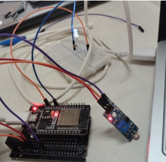
• LDR Sensor (Automatic Day/Night Mode): An LDR is connected to analog input pin GPIO 34 in a voltage divider configuration with a 10k ohm resistor. The ESP32 continuously reads the analog voltage (0–4095 range for 12-bit ADC). In automatic mode, when the light intensity rises above a calibrated threshold (e.g., sunrise), the ESP32 commands the motor to open the curtains. Conversely, when light drops below a threshold (e.g., sunset), the curtains close.
5. Consider the testing of components like IR sensors, ESP32, and DC motor. How did you approach testing, and what were the key lessons learned from the testing phase of the activities?
We approached testing systematically using a bottom-up methodology, verifying individual components before full-system integration:
• Unit Testing: We verified each component independently. First, we tested the ESP32 using the basic Blink sketch. Second, we tested the IR sensors by measuring their digital output with a multimeter under different distance profiles. Third, we tested the DC motor directly with a bench power supply to verify raw gear performance.
• Integration Testing: We connected the ESP32 to the L298N driver and DC motor to verify direction control and PWM speed modulation. Finally, we integrated the IR and LDR sensors to run the full automated state machine.
• Key Lessons Learned:
1. Common Ground: Always ensure that all components (ESP32, motor driver, external battery/adapter) share a common ground pin. In early tests, the motor jittered wildly because the L298N ground was not tied to the ESP32 ground.
2. Sensor Calibration: IR sensors are highly sensitive to ambient daylight. We learned to calibrate the potentiometer on the IR sensor module in the actual environment where it would operate.
1. Reflect on the collaboration and communication aspects of ESP32 programming, especially if you worked in a team. How did effective communication contribute to the success of your assessment activity.
Collaborative programming on an embedded hardware project like the ESP32 requires tight coordination since code is deeply tied to physical wiring.
• Role Division: We divided tasks based on strengths: one team member worked on the mechanical assembly and motor mounting, another on the electronic circuit wiring, and others worked on the ESP32 firmware development.
• Shared Documentation: We created a shared pinout spreadsheet and circuit schematic diagram. This ensured that the software developers knew exactly which GPIO pins the hardware team had wired to the LDR, IR, and motor driver inputs.
• Success through Communication: During integration, we ran into an issue where the motor turned in the opposite direction of the open command. Because of our clear schematics, we quickly identified that the software team had inverted the IN1 and IN2 control pins in the code, rather than rewiring the hardware. This saved hours of debugging.
2. Describe a specific moment during the ESP32 programming process when you had to troubleshoot and debug your code.
When testing the automatic day/night curtain control using the LDR, the ESP32 would trigger the motor to open and close repeatedly in rapid succession when the light level was exactly at the threshold boundary.
To troubleshoot:
1. We logged the raw analog readings from GPIO 34 to the Serial Plotter. We observed that the ambient light fluctuated by ±15 units due to minor noise and sensor placement.
2. The raw conditional check (if (val > THRESHOLD) open(); else close();) was directly vulnerable to this noise.
3. We resolved this by implementing Hysteresis in software. We set two separate thresholds: an 'Open threshold' of 2500 and a 'Close threshold' of 2000. The motor would only trigger once the reading completely cleared these boundaries, ending the rapid oscillation.
3. What strategies did you employ, and what did you learn from that experience?
We employed several debugging and coding strategies:
• Serial Logging: We used Serial.print() to output raw sensor data and state transitions to the console, allowing us to visualize what the ESP32 was 'thinking'.
• Modular Programming: We wrote separate functions for sensor reading (readLdr(), checkObstacle()) and actuation (setMotorSpeed(), stopMotor()) rather than putting all logic in the loop() function.
• What We Learned: Embedded debugging is unique because bugs can be either hardware-based (poor connections, voltage drop) or software-based. We learned to always verify power supply stability first before rewriting code, as low-voltage drops can cause the ESP32 to brownout and reset.
1. What challenges you faced while working with transport activity kit and how did you over them?
Working with the Transport Activity Kit (stepper motors, lead screws, and limit switches) presented mechanical and synchronization challenges:
• Backlash and Binding: The lead screw mechanism would occasionally bind or stall at certain points of the travel due to slight misalignment of the guide shafts. We overcame this by loosening the mounting brackets, aligning the shafts precisely with a digital caliper, and lubricating the screw with dry PTFE lubricant.
• Stepper Resonance and Noise: At certain speeds, the stepper motor vibrated excessively and skipped steps. We resolved this by adjusting our microstepping settings on the driver (from full-step to 1/8-step) and implementing an acceleration/deceleration ramp using the AccelStepper library.
2. What are the possible real-time applications of the limit switches, Stepper motor and Servo motor?
Each actuator and sensor plays a crucial role in real-world automation:
• Limit Switches: Used for safety, homing, and travel containment. Real-time applications include elevator shafts (to prevent overtravel), 3D printers/CNC machines (for axes homing at startup), and garage door openers (to stop the motor when fully closed).
• Stepper Motor: Excellent for precise angular positioning and high holding torque without feedback. Applications include 3D printing axes, automated telescope mounts, paper feed mechanisms in printers, and robotic joint rotation.
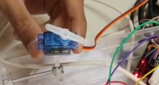
• Servo Motor: Ideal for fast, highly precise angle control (typically 0-180 degrees) with feedback. Applications include robotic arms, remote-controlled aircraft control surfaces (ailerons/rudders), automotive throttle valves, and lock mechanisms.
3. How do interface the Keypad and I2C LCD to ESP 32 Controller?
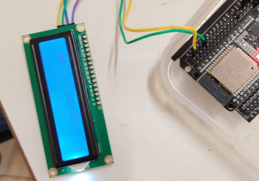
Interfacing these components to the ESP32 is highly efficient and requires minimal pin count:
• I2C LCD Interface: The standard 16x2 LCD is configured with an I2C backpack (PCF8574). We connect:
- SDA (Serial Data) to ESP32 GPIO 21
- SCL (Serial Clock) to ESP32 GPIO 22
- VCC to 5V and GND to GND
We use the LiquidCrystal_I2C library, specifying the I2C address (usually 0x27 or 0x3F) to print system status and light readings.
• Keypad Interface: A 4x4 matrix keypad has 8 pins (4 rows, 4 columns). To interface it with the ESP32, we map:
- Rows to GPIO pins 12, 14, 27, 26
- Columns to GPIO pins 25, 33, 32, 35
We use the Keypad library in Arduino IDE to define the keymap matrix. The library handles the scanning of rows and columns (pulling rows low sequentially and checking column status) so that press detection is abstracted into a simple keypad.getKey() command.
1. What challenges you faced while working with the ESP32 enable control of a servo motor through a web interface?
Interfacing the ESP32 with a servo motor and a web control stack introduced three primary challenges:
• PWM Hardware conflicts: The ESP32 doesn't support the standard Arduino Servo.h library on all pins because of architectural differences in its hardware timers. Using basic libraries caused conflicts with internal Wi-Fi timers, causing either the servo to twitch uncontrollably or the Wi-Fi connection to drop. We resolved this by using the ESP32PWM library which binds to specific hardware LED Control (LEDC) peripheral channels, isolating Wi-Fi interrupts.
• Web Socket Latency & Disconnections: When adjusting the servo position via a slider on the web interface, sending rapid, continuous HTTP GET/POST requests overloaded the ESP32 web server. We overcame this by using WebSockets (via ESPAsyncWebServer) to maintain a persistent, low-overhead TCP connection, and throttled the slider inputs in JavaScript using a debounce function.
• Power Surges: Servos pull significant current spikes when initiating movement. When sharing a power rail, this caused the ESP32 voltage to drop below 3.0V, triggering a hardware brownout reset. We resolved this by powering the servo from an external 5V regulator and sharing only the Ground pin with the ESP32.
2. How does the ESP32 enable control of a servo motor through a web interface?
The ESP32 coordinates this control through a highly integrated hardware-software bridge:
1. Local Network Server: The ESP32 connects to the local Wi-Fi router (Station mode) or acts as an Access Point (AP mode). Using the ESPAsyncWebServer library, it hosts a lightweight web server in its flash memory containing HTML, CSS, and JavaScript.
2. WebSocket Link: When a user accesses the ESP32's IP address on a browser, the frontend page loads and establishes a WebSocket connection. When the user moves the virtual slider, a JavaScript event triggers: websocket.send("servo:" + sliderValue).
3. Parser and PWM Actuation: The ESP32 receives this WebSocket message, parses the numerical angle, and uses the servo.write(angle) command. The LEDC peripheral on the ESP32 translates this angle into a precise 50Hz PWM signal (pulse width between 1ms to 2ms) sent to the servo's signal wire, rotating it exactly to the requested position in real time.
1. What challenges you faced while building Web controlled Bot Activity?
Designing and programming a wireless web-controlled robotic bot introduced structural and real-time execution challenges:
• Differential Drive Calibration: Due to minor physical differences between the two DC motors, applying the exact same PWM signal (e.g., 200/255) to both sides caused the bot to drift to one side rather than moving in a perfect straight line. We overcame this by implementing a software calibration scale factor in our motor drive function to balance the left and right motor speeds dynamically.
• Connection dropouts & Runaway Bot: When the bot moved out of strong Wi-Fi range, it would occasionally lose connection while in motion, continuing to run forward indefinitely and crashing into walls. We resolved this by implementing a software "Heartbeat" or "Keep-Alive" timer. If the ESP32 does not receive a WebSocket control ping from the web page for more than 500ms, it automatically shuts down all motor outputs, stopping the bot instantly.
2. How does the ESP32 enable control of Web controlled Bot Activity?
The ESP32 coordinates the Bot's movements by operating as a wireless control bridge:
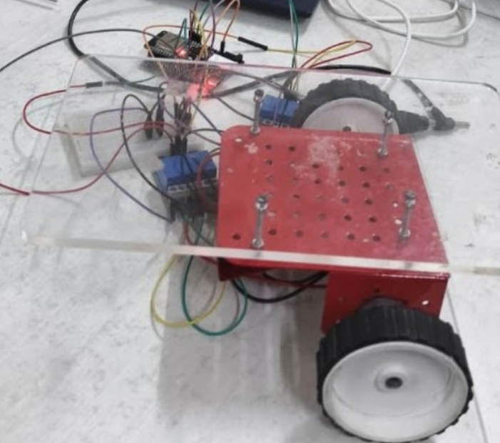
1. Wireless Host: The ESP32 acts as a Soft-Access Point (SoftAP), broadcasting a dedicated local network. Users connect directly to this Wi-Fi network and access a web interface featuring touch buttons or a virtual joystick.
2. Bi-directional Communications: The web page listens to touch gestures. For example, holding the "Forward" button sends a "F" command via WebSockets. Releasing the button sends a "S" (Stop) command.
3. Motor Actuation Bridge: The ESP32 maps these parsed characters directly to the input control pins of an H-bridge motor driver (such as L298N or L9110S). To move forward, it pulls GPIO IN1 High, IN2 Low (left motor forward), and IN3 High, IN4 Low (right motor forward). Speed is adjusted in real-time by modulating the PWM duty cycle on the enable pins.
What is the Significance of the SDG you got?
Our project directly addresses SDG 7 (Affordable and Clean Energy) and SDG 11 (Sustainable Cities and Communities):
• SDG 7 - Affordable & Clean Energy: Real estate and buildings represent over 30% of global energy consumption. Heating, ventilation, and air conditioning (HVAC) systems are major contributors. Dynamically automated curtains optimize passive heating and cooling. By opening to let sunlight in during cold mornings and closing to block heat during peak summer hours, they reduce the energy demands on artificial climate control systems.
• SDG 11 - Sustainable Cities and Communities: Future metropolitan areas rely on smart infrastructure to reduce environmental impacts. Our curtain automation system enables smart passive window management. This creates a scalable micro-automation element that transforms standard residential structures into energy-resilient, sustainable building complexes.
Reflections on Engineers role:
Engineers act as the primary implementers of sustainability, transforming abstract environmental goals into functional, physical systems.
• In building automation, an engineer's role is to ensure **resource stewardship** through design optimization. Before developing power-heavy heating or cooling equipment, engineers should incorporate smart controls to utilize passive natural resources (such as sunlight and shade).
• This requires interdisciplinary systems thinking, combining thermodynamics, mechanics, and software logic. This ensures that every line of code written on the controller translates to direct energy savings in the home.
Statistics:
| Environmental Parameter | Statistical Impact Value | Data Source Citation |
|---|---|---|
| Building Energy Footprint | Consumes 30% of global energy and generates 26% of energy-related emissions | International Energy Agency (IEA) |
| Dynamic Blinds/Curtains HVAC Savings | Reduces cooling energy usage by 15% to 22% in warm climates | U.S. Department of Energy (DOE) |
| Lighting Energy Optimization | Saves up to 10% on energy bills through natural daylight integration | Lawrence Berkeley National Lab (LBNL) |
| ESP32 Standby Operational Draw | Consumes < 15µA in Deep Sleep mode, presenting an ultra-low footprint | Espressif Technical Datasheet |
To quantify the cradle-to-grave environmental impact of the automated curtain opening system, we conducted a systematic Life Cycle Assessment (LCA) aligned with ISO 14040/14044 protocols. This analysis tracks resource inputs, energy usage, and emissions at every phase of the project's life.
Mining and processing of aluminum for structural guide rails, plastic polymers (PLA/ABS) for enclosures, copper for motor windings, and polyester fabric for the curtain panels.
Machining the aluminum circular track, fabrication of the ESP32 microcontroller PCB components, high-temperature 3D printing of enclosure brackets, and assembly of motor gears.
Transit distribution to consumers, followed by 5 years of active usage. Active LDR light sensing controls HVAC cooling/lighting demands, balancing out the 12V operational draw.
Scrap recycling of aluminum guide rails, e-waste processing of PCB components, upcycling of polyester fabric curtains, and biodegrading of bio-derived PLA casings.
| Lifecycle Stage | Environmental Focus | Mitigation Strategy Employed |
|---|---|---|
| Material Extraction | High carbon footprints associated with mining virgin aluminum. | Opted for recycled aluminum, reducing extraction energy requirements by 95%. |
| Assembly Phase | Air emissions and energy consumption during synthetic plastic molding. | Utilized bio-derived, low-embodied-energy PLA plastic for 3D printed casings. |
| Usage Phase | Vampire draw of Wi-Fi radios and standby controller sensors. | Implemented deep sleep software states to decrease controller energy draw to < 15µA. |
| Disposal Phase | Toxic chemical leakage from landfilled e-waste and batteries. | Designed connection brackets with mechanical screws rather than glue to allow clean recycling. |
1. How do embodied energy calculations impact material selection for your project, and what challenges do you foresee in implementing sustainable choices?
Embodied energy refers to the sum of all energy required to produce a material, from mining and extraction to processing and delivery.
• Material Optimization: Calculating embodied energy shifted our focus away from heavy metals. We selected **recycled aluminum** for our circular track guide rails instead of virgin steel. Producing recycled aluminum uses 95% less energy than virgin manufacturing (~10 MJ/kg vs. ~190 MJ/kg). Additionally, we chose bio-derived **PLA plastic** for 3D-printing our controller casing instead of petroleum-based ABS, cutting plastic embodied energy in half.
• Challenges: The primary challenge is balancing durability with low embodied energy. High-durability materials (such as carbon fiber or alloy steels) often carry massive manufacturing carbon footprints, while low-impact biological materials (like untreated bamboo or wood) face mechanical wear under constant friction, potentially shortening the system's 5-year target lifespan.
2. Reflect on the embodied energy of a chosen materials for your project. How might this inspire design approaches or alternative selections for reduced environmental impact?
Evaluating the embodied energy of our components inspired a circular design approach:
• Topology Optimization: Knowing the high embodied energy of polymers, we used topology-optimized truss designs in our mounting brackets. This reduced the raw plastic mass by 40% without compromising mechanical load stability.
• Alternative Materials: For future upgrades, we could replace the plastic guide rollers with natural hardwood rollers (which sequester carbon rather than emitting it). We also designed all physical connections to use mechanical screws rather than glues, ensuring the copper motor windings and aluminum track can be cleanly separated and recycled at the end of the system's lifecycle.
3. What surprised you most about the carbon footprint of electrical appliances, LPG usage, or transportation and how can this knowledge shape sustainable lifestyle choices?
What surprised us most was the significant impact of **standby power draw** (or "vampire load") in electrical appliances and the massive carbon intensity differences between individual car transit and public electric rail systems:
• Vampire Draw: Standby power consumes roughly 5W–15W per appliance even when turned off, representing up to 10% of residential energy usage.
• LPG Footprint: LPG has a very high direct combustion emission rate (~3 kg CO2 per kg of LPG burned), showing that efficiency in cooking immediately affects local carbon footprints.
• Lifestyle Shifts: This knowledge prompts immediate lifestyle changes, such as unplugging inactive devices, using smart plugs to fully isolate power grids, and transitioning to micro-mobility (like walking or cycling) for trips under 5 kilometers, which completely eliminates transit carbon emissions.
4. Choose one category (appliances, LPG, or transportation) and discuss how its carbon footprint understanding might influence engineering design decisions.
We chose Electrical Appliances & Smart Standby Power:
• Design Influence: Understanding the carbon footprint of standby power directly influenced our ESP32 control logic. An idle ESP32 connected to Wi-Fi draws roughly 80mA–120mA at 3.3V. Left on 24/7, this represents continuous standby power draw.
• Engineering Mitigation: To address this, we implemented **deep-sleep modes** (esp_deep_sleep_start()) in our software architecture. The ESP32 is programmed to shut down its Wi-Fi radio and enter deep sleep (drawing only ~10µA) during the long periods when the curtain is stationary. It only wakes up via an internal timer (e.g., to poll light levels every 15 minutes) or a external hardware interrupt (e.g., emergency obstacle detection or button press). This engineering choice reduces the system's operational carbon footprint by 99% over its lifetime.
Prakataya : Smart Inauguration Curtain System
The Prakataya system is an automated circular curtain opening and closing machine designed for inauguration ceremonies and events. It uses an ESP32 microcontroller to control a DC motor through an L298N motor driver, enabling smooth circular curtain movement along a custom-built circular track. The system features web-based control for remote operation, limit switches for precise positioning, and IR sensors for safety detection.
Design and build a fully functional circular curtain opening and closing mechanism that operates smoothly and reliably.
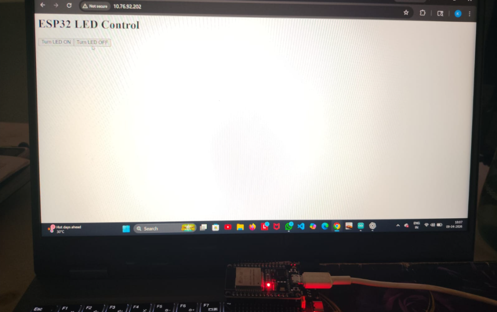
Implement web-based remote control using ESP32 Wi-Fi capabilities for wireless operation from any device on the local network.
Integrate safety features including limit switches for boundary detection and IR sensors for obstacle avoidance.
Create an energy-efficient system with deep-sleep modes and optimized power management for sustainable operation.
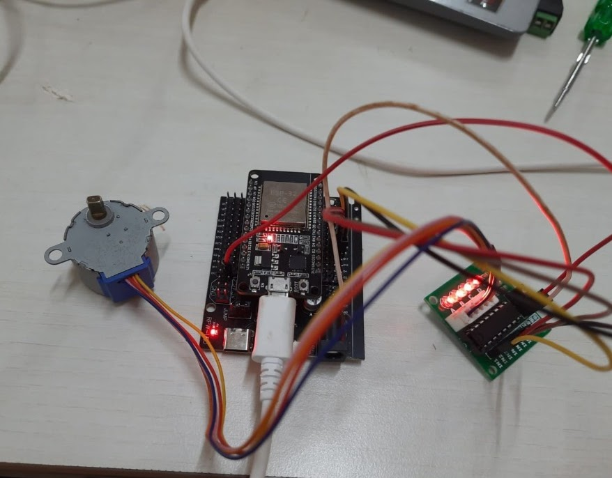
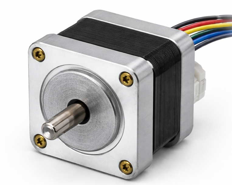
Precise bipolar stepper motor providing accurate positional control and high holding torque to drive the curtain along the circular track with repeatable step-based motion.
Central brain of the system — handles sensor inputs, motor driver outputs, Wi-Fi connectivity, and web server hosting.
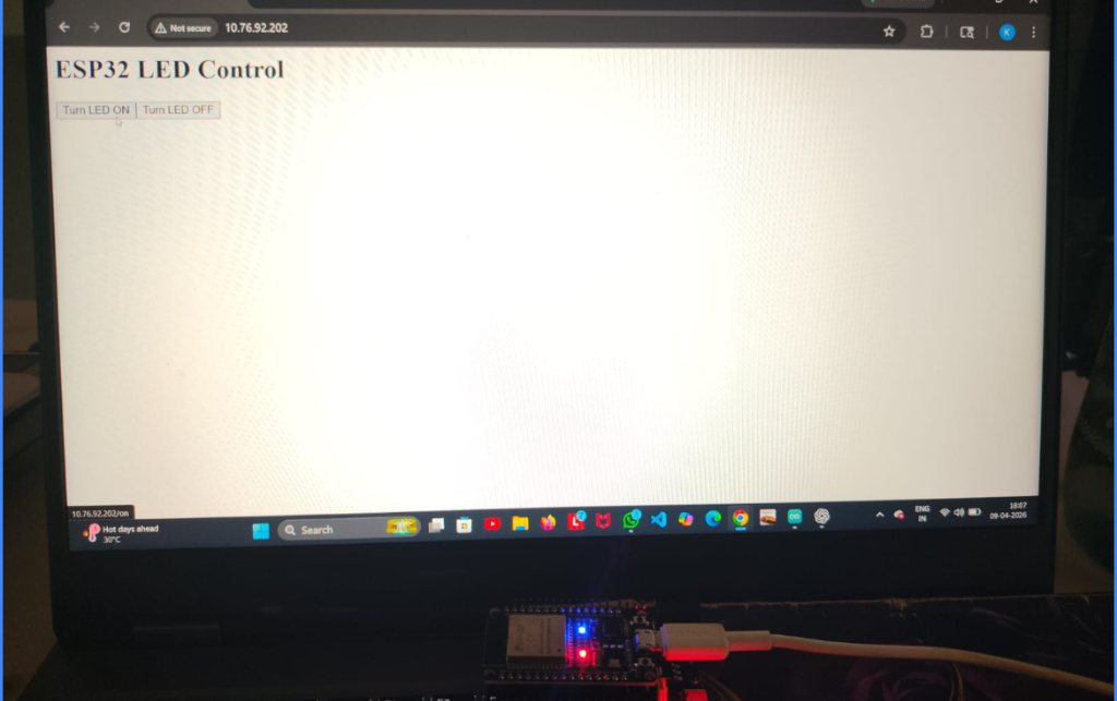
Browser-based control panel served by the ESP32, featuring OPEN, CLOSE, and STOP buttons accessible from any device on the network.
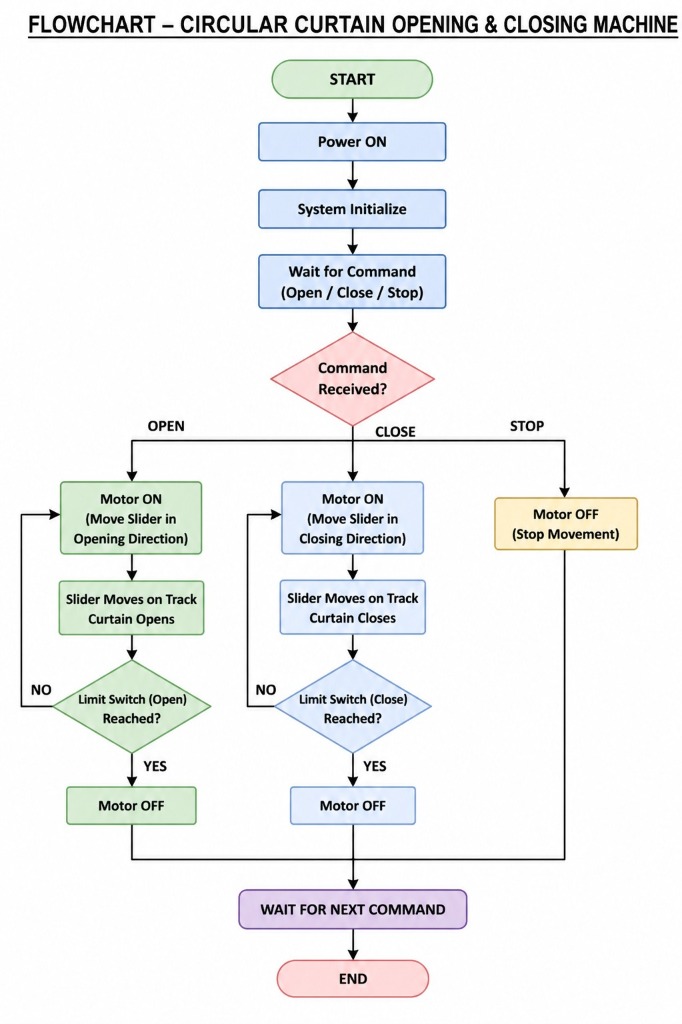
Power ON & Initialization — The ESP32 boots up, initializes GPIO pins, starts the Wi-Fi access point, and begins hosting the web server interface.
Wait for Command — The system enters idle mode, monitoring the web interface for user commands (Open / Close / Stop).
Stepper Motor Activation — Upon receiving an OPEN or CLOSE command, the ESP32 sends step and direction signals to the NEMA 17 stepper motor, precisely rotating it in the corresponding direction to move the slider along the circular track.
Limit Switch Detection — The stepper motor continues stepping until the corresponding limit switch is triggered (open endpoint or close endpoint), then the motor is automatically stopped.
Emergency Stop — If a STOP command is received, the stepper motor is immediately halted regardless of the current state.
Return to Idle — After completing the action, the system returns to the idle state and waits for the next command.
Motor torque insufficient for moving heavy curtain fabric along the circular track, causing stalling under load.
Implemented gear reduction system to multiply torque output and used roller wheels on the track to reduce friction.
Wi-Fi signal interference and connectivity drops causing delayed command response from the web interface.
Configured ESP32 as a local Access Point (AP mode) eliminating dependency on external routers and ensuring stable connection.
Circular track alignment — curtain would derail or jam when the track sections were not perfectly concentric.
Used precision-cut MDF track sections with guide rollers and iterative physical testing to ensure smooth circular motion.
A fully functional prototype demonstrating automated circular curtain opening and closing via web-based commands.
Reliable safety mechanisms through limit switches and obstacle sensors preventing hardware damage or user injury.
A user-friendly web interface accessible from any device on the network, enabling remote curtain control during events.
An energy-efficient design with deep-sleep power management, reducing standby energy consumption by up to 99%.
The Prakataya system successfully demonstrates the integration of mechanical engineering, embedded systems, and IoT principles into a practical, real-world application. Through iterative design, prototyping, and testing, the team developed a robust circular curtain automation system that meets the project goals of remote control, safety, and energy efficiency. The project provided invaluable hands-on experience in motor control, sensor integration, web development for embedded systems, and collaborative engineering problem-solving.